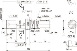
Engineering drawings are a great way to communicate design intent for CNC machined parts that require tight tolerances or other special requirements. The following 9 tips will teach you how to create better technical drawings, clearly communicate your key needs, and save time and money.
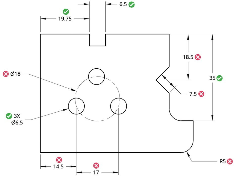
- Label only critical and measurable characteristics
In CNC machining, all dimensions can be derived from the 3D model. Therefore, only critical inspection dimension and thread information is required on the 2D drawing.
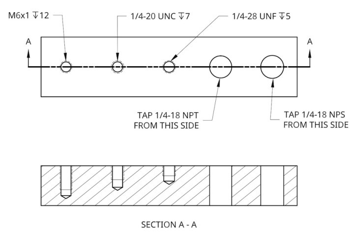
- Communicate hole tapping requirements, thread size and depth to the design team
Tread depth is difficult to measure accurately; therefore, the depth call is always considered a minimum value.
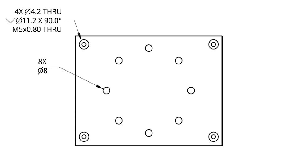
- Merge calls when multiple identical functions exist in a view
Dimension only one of the features, and dimension it as “#X DIM”, which means the feature exists “number of times” in this view. For example, “4X 10-32 tapped” means there are 4 10-32 tapped holes in the view.
- Communicate assembly intent for key features
Please provide assembly drawings or instructions if the entire assembly is being machined. Or, if you’re installing off-the-shelf hardware yourself, provide the part number so the mechanic can look it up.
E.g.:
Drilled holes for press-fit/slip-fit/clearance fit McMaster part number 97395A452
Tap for M3 Helicoil insert McMaster part number 91732A645
- Provide supplier and part number on drawing when mounting hardware is required
Note that “Press Fit M4 Dowels” does not give machine shop dowel length or material information.
- Keep optional secondary operation calls on the sheet
Suppose secondary operations (like polishing and anodizing) are optional and not critical. It is best to request a quote and lead time for these add-ons separately to understand the additional time and cost. In our experience, many people don’t find ancillary operations not worth the extra lead time and cost until the late prototyping stage.
Likewise, if you are not sure what material to use, or are trying several different materials, remove the material from the drawing to avoid confusion in production.
- Avoid over-dimensioning or over-tolerance when designing
Often, only a few features on a part are critical to its function, so you want the mechanic to pay special attention to these features. Critical requirements disappear into the noise when oversizing, so only specify tolerances for mission-critical features. Oversizing can also drive up the cost of the prototype.
- Accuracy capabilities requiring tolerances lower than standard hand metrology tools
- Don’t automatically expect all GD&T controls to be checked
We have no objection to using GD&t controls to communicate design requirements. We appreciate the efficiency of the system compared to traditional linear dimensioning. However, some GD&T controls cannot be easily verified with manual metrology tools, which are the standard for rapid turnaround prototyping.
We typically see the following GD&T control symbols on prototype diagrams:
- Flatness
- Surface profile
- Applied to the true position of the hole and boss centre
Standard practice is to skip these marked inspections unless the machine shop specifically instructs to provide a CMM inspection report.
at last
Oversizing in designs (dimensioning too many non-critical features) and tight tolerances (unnecessarily requiring features to be less than +/- 0.05 mm or +/- 0.002 inches) are major causes of lost money in prototyping.
These tips can save time during the design process and money during the prototyping process. When you desperately need to dimension a feature, ask yourself: Is this critical to the assembly? Is this need measurable? You could name that dimension only if you answered “yes” to both questions.


